Introduction
I had stumbled across this thread on Bimmerpost a few months ago and became interested in integrating my VSC-1 Exhaust Controller directly into my steering wheel, instead of having to reach up and hit the garage opener to actuate the exhaust valves. Additionally, I could never remember which garage opener button would open or close the valves (first world problems, I know). Initially, I had planned on reusing the electrical connections – by tapping into the pins below – however, after probing the circuit, I came to realize that these switches weren’t just simple switches.

Although I haven’t tested the circuit with it attached the car and the car powered on (as I don’t want to break anything), my guess would be is that there is some sort of multiplexing going on, thus 4 input and 4 output pins could support 4×4=16 combinations. Crucially, this tells me that I cannot treat these switches as “dumb” switches and attempt to use the switch to create a short to activate the button on my remote. I could be wrong though, and it would be awesome to be able to power the remote (which is 9V by the way, which means I would also need to down-convert the voltage from 12V) directly from the cluster.
Once I realized this, I shelved the project for a bit. It wasn’t until a little later, when I brought this project idea up with my father, he made a suggestion to use a physical switch over the existing electrical contacts, which would be actuated by the same M1/M2 buttons. I decided to order a set of small momentary switches from Amazon to test this suggestion out.
Tools and Materials
- 10mm Socket for battery disconnect
- 2 Small towels for trunk
- T20 Torx for steering wheel disassembly
- Small Phillips Head Screw driver
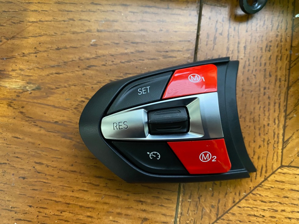
- Non-Blank M1/M2 Buttons
- Remote that can be disassembled, powered, and fit inside the steering wheel
- Electrical Tape
- Duct Tape
- Soldering Iron and Solder
- (Recommended) Soldering Station with Magnifying Glass
- Small switches such as these
Soldering
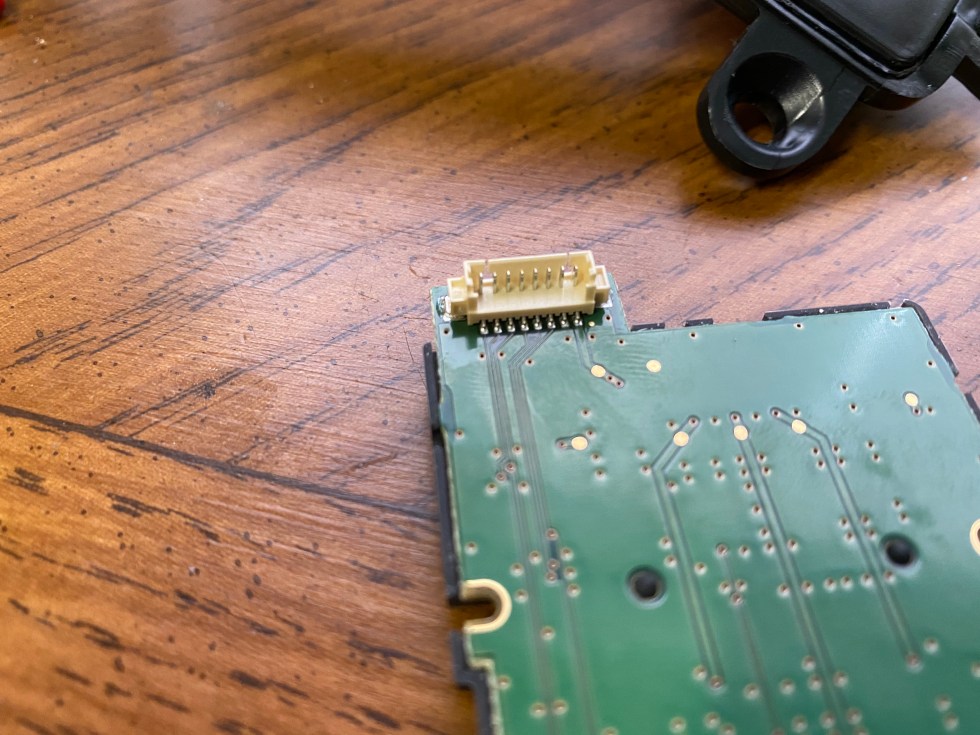
The 5mm buttons I bought as well as the contact points on the remote were relatively small, so it is helpful to have a thin tip on the soldering iron as well as a jig to hold the pieces. A larger button with larger contacts may have made the process easier.


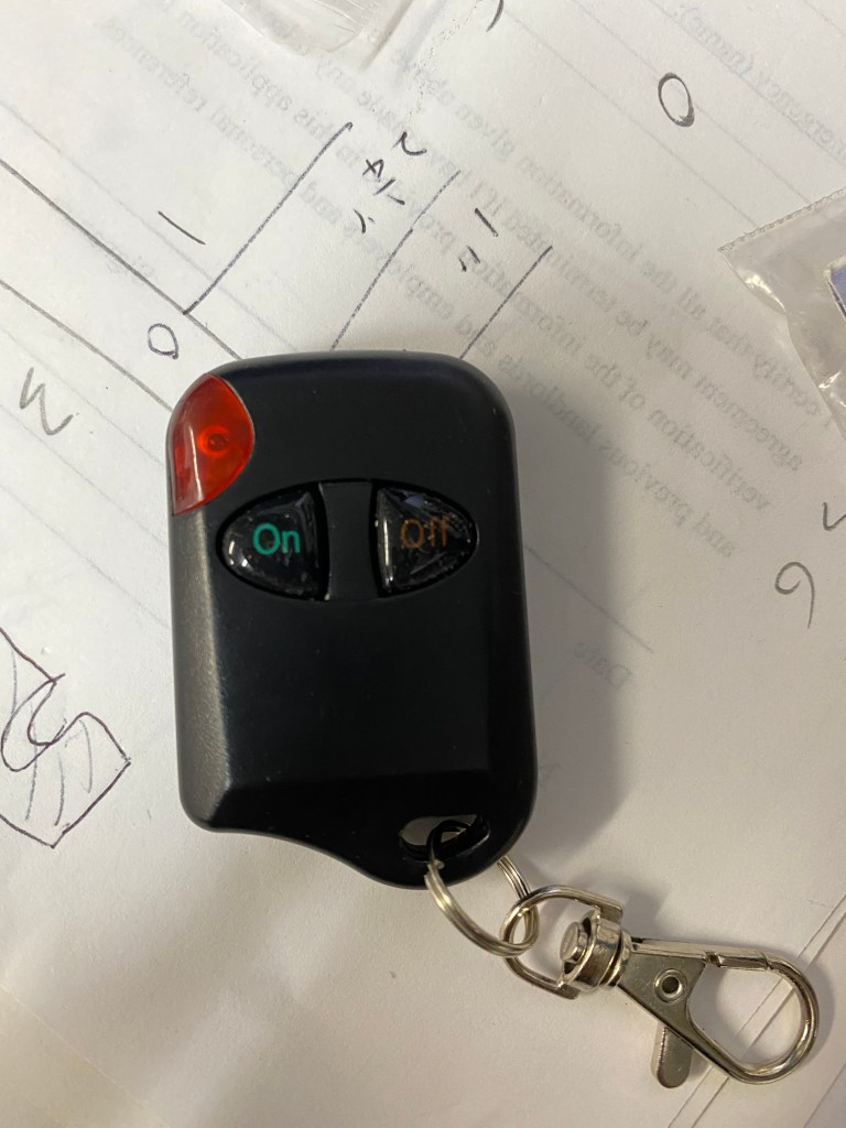
Below is the original remote, with a 9V battery and two buttons – ON and OFF. In order to control the switch via the M1 and M2 buttons, I will need to create a short across the contacts circled below.

I did consider removing the existing switches but since this was my first time and I wasn’t sure if it would work, I opted to leave the switches there.

The wiring itself only needs to be about 3-5 inches – I used roughly 1 ft and found that was way too much wire, but luckily I had no issues tucking it away in the steering wheel.
Disconnect the Battery
As with anything related to the electrical components, and especially the airbag, it is a good idea to disconnect the battery first.
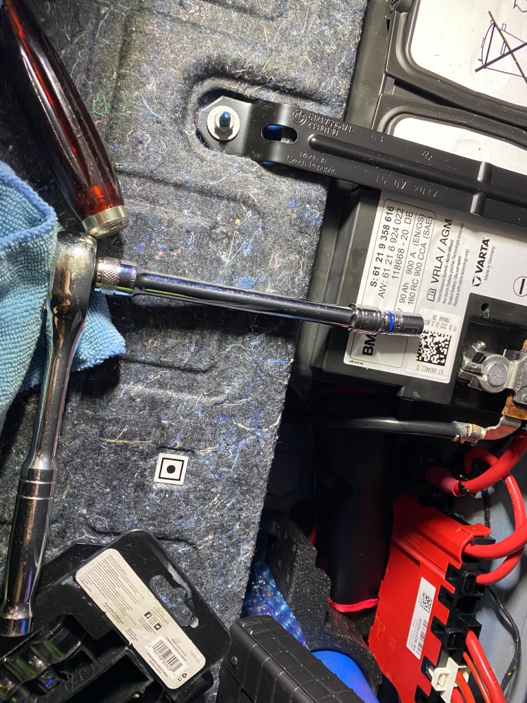
Use the 10mm socket (extension not required) to disconnect the ground wire from the battery terminal. A flathead may be required to dislodge the connection after loosening the bolt. 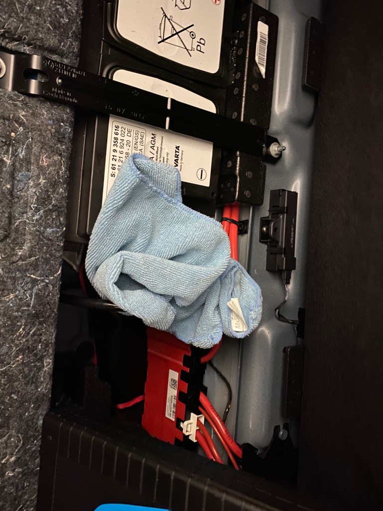
Wrap the loose ground wire in a cloth to prevent it from accidentally touching something it shouldn’t. 
Tip: Stick a cloth into the latch to prevent the trunk from closing. If the trunk closes when the battery is disconnected, you will have a bad time.
Disclaimer: If you aren’t comfortable with disconnecting the battery and airbag, I would not recommend this project.
Disassemble Steering Wheel
Once the battery is disconnected, I like to wait a few minutes before removing the airbag to allow any capacitors to discharge. The airbag can be removed by sticking a tool (in this case, I used my T20 torx tool) into the small holes on both sides of the steering and releasing the clips. Watch this video for detailed instructions. Note: The blanks should be replaced with the M1 and M2 buttons as well. I would also recommend to apply some lithium grease (or any other low viscosity grease) to the buttons, otherwise they will be quite sticky because, unlike the M3/M4, there wasn’t a functional button there to be begin with. I used silicone grease, but that was too thick so I may clean it out and use lithium grease in the future.
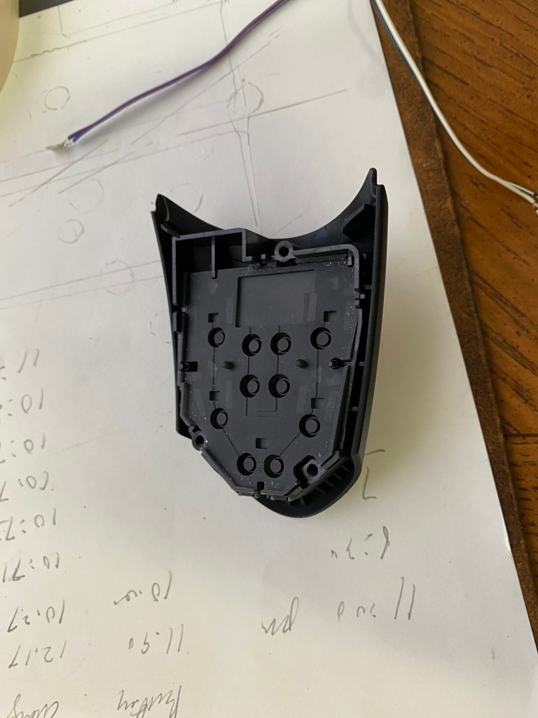
For this project, we only need to remove the left side cluster. On the back of the cluster there is a T20 screw will need to be removed first. Then the cluster will have 3 Philips-head screws that should be removed. Make sure you don’t lose any of the buttons (there are 2 or 3 loose pieces) when separating the halves.
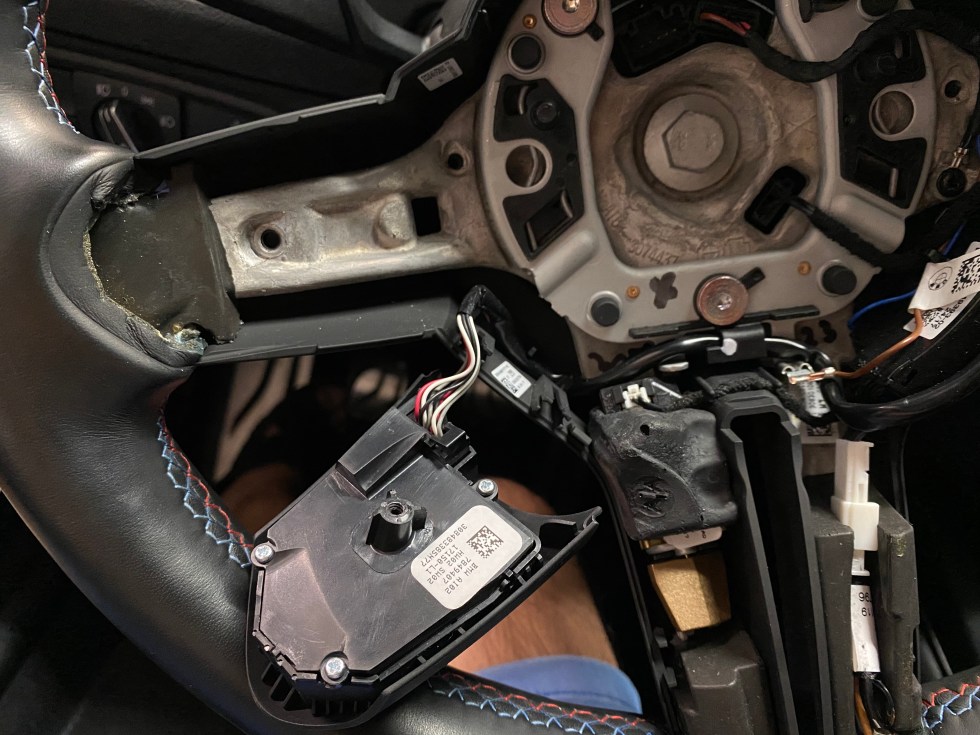
I only needed to remove the rubber and top-shell of the cluster from the car, but this will depend on how you decide to mount the switch to the cluster.
Attach the New Switches to the Cluster
Next, we need to attach the switches to the back of the cluster. You can go about this in a few different ways:
- Glue directly to the PCB
- Glue to the back of the rubber part (although need to be careful this does not interrupt the mechanism that allows the switch to activate)
- Duct tape to the back of the rubber part
- Create an adapter (via 3D printing or other method) to seat the switch into the rubber indent
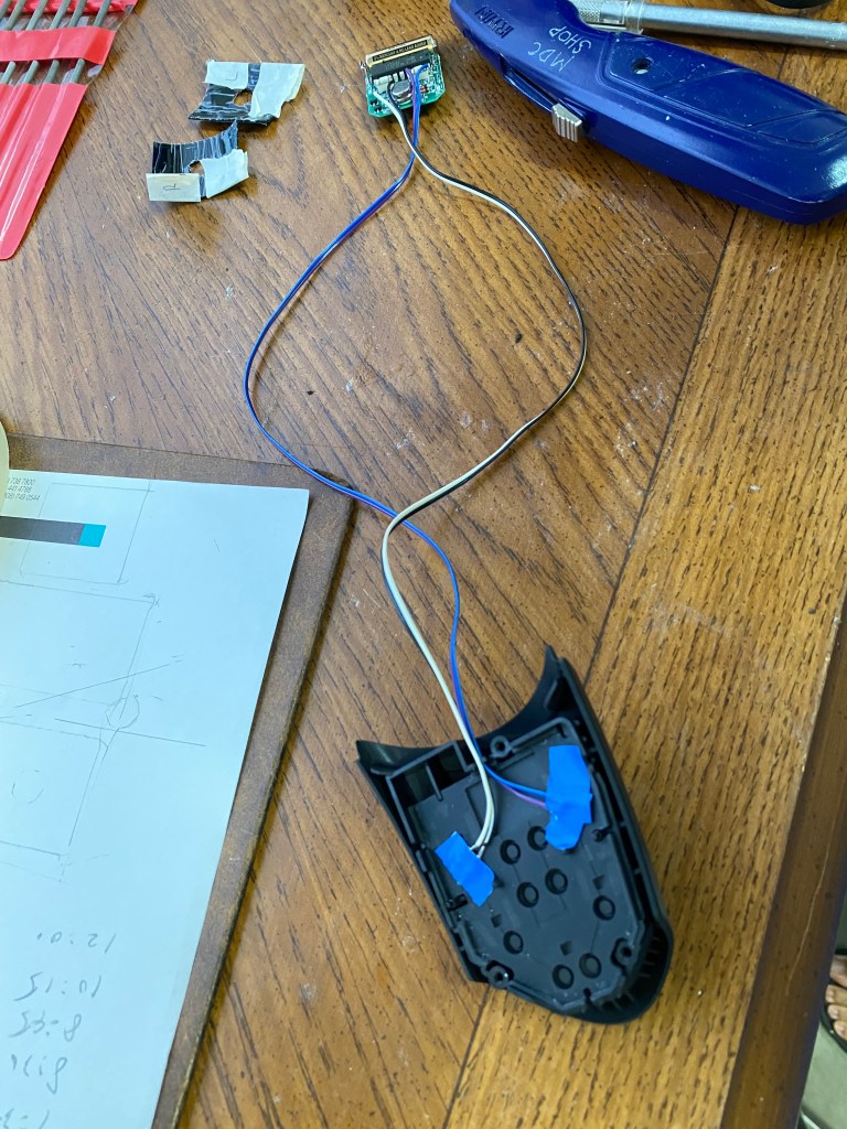
In the image below, I opted for option 3 since it was easily reversible if this didn’t work out. I think in the future I will go with a more robust solution (such as option 4 if possible), but for now it works. Additionally, when you assemble the entire unit, there is some clamping pressure that will prevent the switches from moving.


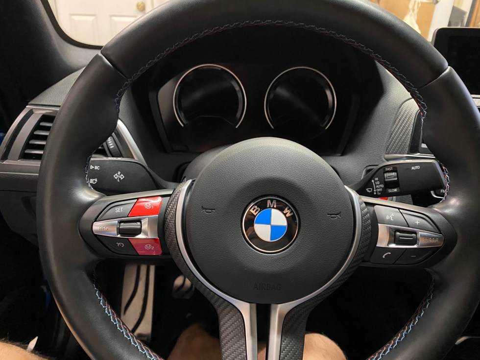
Here is a photo of the left cluster reinstalled with the torx screw in the back.

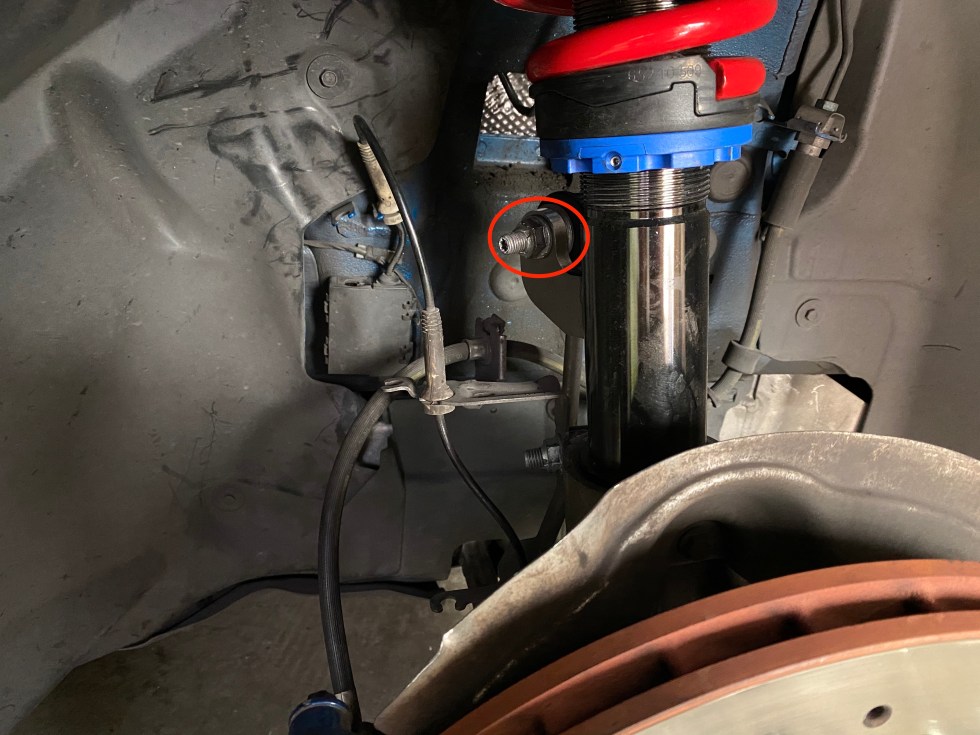
I tucked and taped the controller on the left side (I wrapped the controller completely in electrical tape to prevent any shorting out) – it is hard to see so I circled the area in blue. When taping the controller and wiring down, make 1000% sure that you can still insert your tool to release the clip (circled in red). If your wires or controller are in the way, you will have a bad time trying to take off your airbag in the future.

Wrapping Up
All there is left to do is to reassemble the steering wheel and making sure nothing is hitting the wires. There is plenty of space in the steering wheel so this should not be an issue if done correctly.

Summary
All in all, the project wasn’t too challenging once the strategy was figured out. The most difficult and longest section would probably be soldering the tiny connections together. This project also requires that you have a wireless exhaust controller (or be willing to wire through the clock spring), but I believe this covers the large majority of aftermarket exhaust systems, including the M Performance Exhaust from BMW – however, that remote is shaped differently so I cannot comment on whether or not the circuitry would fit inside the steering wheel. This is a nice and fairly OEM looking solution that makes it very easy to open and close your exhaust valves. This method could also be used to activate anything that relies on a switch but does not need to go through the car itself.
Future Considerations
- Spray paint the M1/M2 buttons with exhaust icons
- 3D Print some sort of adapter so the switch is locked into the rubber indent (rather than relying on tape)
- Find a better way to route the wires – by using a dremel to make room or some other method – so the assembly can be closed completely
- Find a 12V power connection inside the steering wheel, then down convert to 9V to replace the need for a battery. I expect the battery to last a long time however, so this is a low priority.